As you build a link chart from a knowledge graph, you can change how entities are arranged to better visualize the relationships between them.
By default, entities are arranged using the radial tree layout. However, several other layouts are available to choose from: force directed, community, simple, radial tree, smart tree, and geographic. The layout used to arrange the contents of a link chart is indicated in the link chart Context Toolbar and is referred to as the current layout. Various operations that act on this link chart will use the current layout to process results. For example, when you add entities and their relationships, they are added in a manner that is appropriate for the current layout.
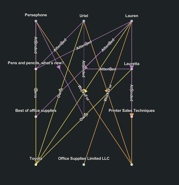
Simple layout
Simple  layout arranges entities in a
regularly spaced lattice pattern, where the size of the grid
depends on the number of entities.
Force Directed layout
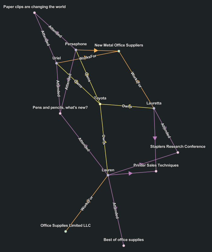
The Force Directed  layout algorithm considers the link chart as if it were a mechanical
system. The entities repel each other like two magnets aligned with
the same poles facing each other, while they are attracted to each
other by the relationships that join entities together. The
algorithm iteratively reviews and places entities and evaluates the
forces until equilibrium is reached. This layout allows you to
visualize entities in clusters that emphasize how they are
connected.
Community layout
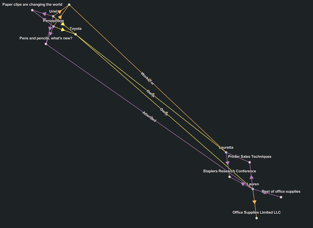
The Community  layout finds
communities, which are groups of entities that are closely related
to each other. A force-directed layout is then used to arrange the
communities. The attraction forces along relationships between
entities of different communities are relaxed so that different
communities are more spread out than with the standard organic
layout.
Geographic layout
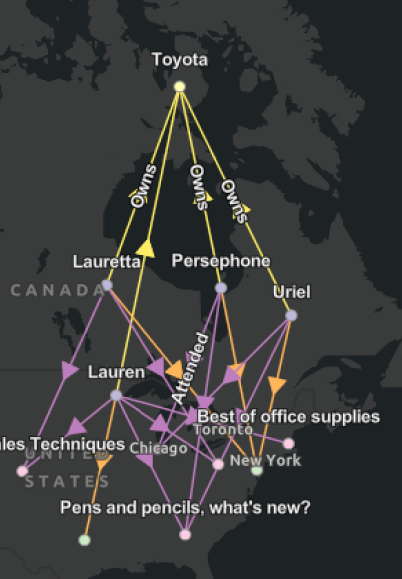
The Geographic  layout
arranges spatial entities geographically using their geometry.
Spatial entities where the entity has a null geometry and
nonspatial entities are also displayed on the link chart, but their
placement and arrangement are determined using the force directed
layout.
layout
arranges spatial entities geographically using their geometry.
Spatial entities where the entity has a null geometry and
nonspatial entities are also displayed on the link chart, but their
placement and arrangement are determined using the force directed
layout.
Your organization's basemap is used by default as a backdrop to provide spatial context.
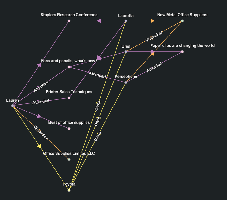
Smart tree layout
The Smart Tree  layout arranges
entities and their relationships as in nature, where the tree
starts from the trunk and all branches move out from that point. In
the link chart, the root entity is the starting point, positioned
at the left. The entities related to the
root entity are then lined up in a row to the
right of the root entity, from top to
bottom in this example. Any entities related to those items
that aren't already present in the link chart are added as another
row closer to the bottom, and so on.
The algorithm identifies the entity associated with the smallest network topology index and uses it as the root entity.
Radial Tree layout
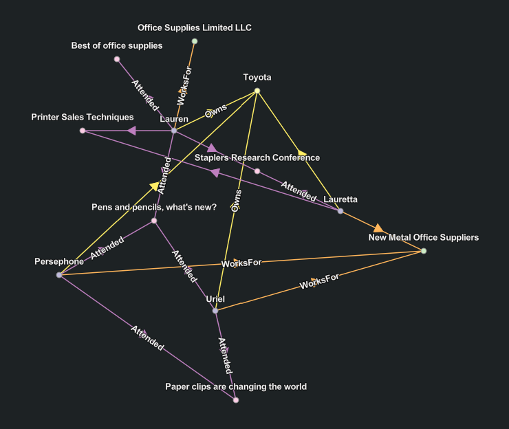
The Radial Tree  layout places the root entity for the tree in the center of a circle. All leaf entities for the tree are positioned around the outer edge of the circle. Entities at each level of hierarchy in the tree are arranged in concentric circles between the root entity and the outer circle.
The radial tree layout is the default layout used to arrange entities and relationships when a link chart is created.
Hierarchical layout
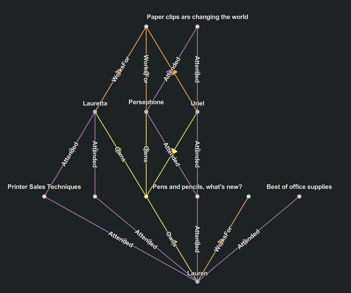
The Hierarchical  layout is arranged similarly to radial tree layout. However, an attempt is made to orient the majority of the relationships from the bottom to the top where the origins for the relationship are positioned at the bottom and destination entities are positioned at the top.
The algorithm will attempt to limit the number of places in which the lines representing relationships cross each other. In contrast with the radial tree layout, relationships are not allowed between entities at the same level in the link chart with the hierarchical layout.
Apply a different layout to your link chart
A link chart's current layout is selected in link chart Context Toolbar in the Layout Options  dropdown. For example, if the link chart is currently using the default force directed layout, the force directed layout is selected in the Layout Options
 dropdown.
- Click Layout Options
 in the link chart Context Toolbar.
 - Click a different layout in the dropdown
All entities and relationships on the link chart are rearranged according to the new layout.